Non Destructive Testing Services
Liquid Penetrant Inspection
Liquid Penetrant Inspection (LPI) is a widely applied and low-cost inspection method used to locate surface-breaking defects in all non-porous materials (i.e., metals, plastics, or ceramics).
LPI is based upon capillary action, where a low surface tension fluid penetrates into clean and dry surface-breaking discontinuities. A Penetrant may be applied to the test component by dipping, spraying, or brushing.
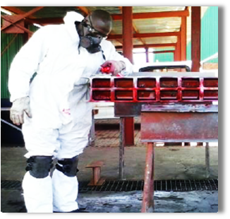
After adequate dwell time has been allowed, the excess penetrant is removed and a developer is applied. The developer helps to draw penetrant out of the discontinuity so that an invisible indication becomes visible to the inspector. Inspection is performed under ultraviolet or white light, depending on the type of dye used - fluorescent or non/fluorescent (visible).
We perform the test in accordance to ASTM E165: Standard Test Method for Liquid Penetration Examination.
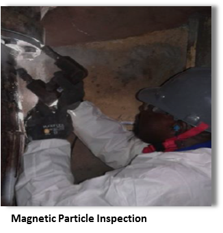
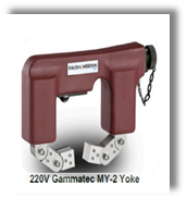
Magnetic Particle Inspection
Magnetic Particle Inspection (MPI) can be regarded as a combination of two NDE methods namely magnetic flux leakage and visual testing. Magnetic flux leakage is a phenomenon wherein the magnetic field is expanded from its normal path due to the presence of the air gap normally induced by the presence of the discontinuity (i.e., crack) on metallic material.
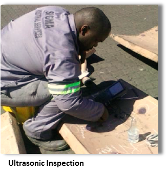
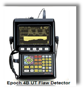
Ultrasonic Inspection
Ultrasonic testing (UT) is a family of non-destructive testing techniques based on the propagation of ultrasonic waves in material tested through various probes.
In most common UT applications, very short ultrasonic pulse-waves with centre frequencies ranging from 0.1-15 MHz, and occasionally up to 50 MHz, are transmitted into materials to detect internal flaws or to characterize materials.
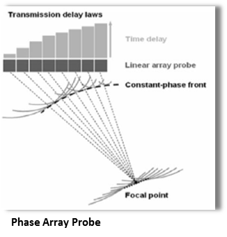
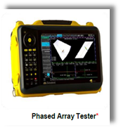
Phased Array
Phased array ultrasonic (PA) is an advanced method of ultrasonic testing (UT) that has wide applications in industrial non-destructive-testing. The term phased refers to the timing, and the term array refers to the multiple elements. PA UT is based on principles of wave physics.
In contrast to a conventional UT manually scanned probes that emit fixed direction beam, the beam from a phased array probe can be moved electronically, without moving the probe, and can be swept through a wide volume of material at high speed.
The beam is controllable because a phased array probe is made up of multiple small elements, each of which can be pulsed individually at a computer calculated timing.
Wall Thickness
Ultrasonic thickness measurement (WT) is a method of performing non-destructive measurement of a thickness of a solid element (typically made of metal), based on the time taken by the ultrasound wave to return to the surface. We perform this this type of measurement with an ultrasonic thickness gauge.
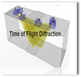
Time of flight diffraction
Measuring the amplitude of reflected signal is a relatively unreliable method of sizing defects because the amplitude strongly depends on the orientation of the crack. Instead of amplitude, Time of flight diffraction (TOFD) uses the time of flight of an ultrasonic pulse to determine the position of a reflector.
In a TOFD system, a pair of ultrasonic probes sits on opposite sides of a weld. One of the probes, the transmitter, emits an ultrasonic pulse that is picked up by the probe on the other side, the receiver.
In undamaged pipes, the signals picked up by the receiver probe are from two waves: one that travels along the surface and one that reflects off the far wall.
When a crack is present, there is a diffraction of the ultrasonic wave from the tip(s) of the crack. Using the measured time of flight of the pulse, the depth of a crack tip can be calculated automatically by simple trigonometry.
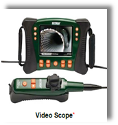
Bore/ Video scope
A borescope is an optical device consisting of a rigid or flexible tube with an eyepiece on one end, an objective lens on the other linked together by a relay optical system in between.
The optical system in some instances is surrounded by optical fibres used for illumination of the remote object.
An internal image of the illuminated object is formed by the objective lens and magnified by the eyepiece in order to presents it to the viewer's eye.
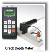
Crack Depth Meter
Crack depth determination with the potential probe method is based on the measurement of the electrical resistance between two points on the surface of a metallic workpiece. A probe with four spring-loaded and gilded contact pins is positioned across the crack to be measured on the workpiece.
Equipment Capabilities
 *Equipment to be outsourced from reliable supplier upon request
Current Equipment and Instruments
- 6x Magnetic Particle Test Yokes,
- 1x Epoch 4B Ultrasonic flaw detector with 12 various Probes
- 4x Digital Ultrasonic Thickness Tester ,
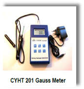
- 2x Light Meter, 2X Pie Gauge; 2x Gaussmeter and 2x Castrol Strips
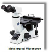
- 1x Metallurgical Microscope
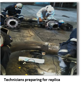
- 10x Sets of Replica Tools
Outsourced Equipment and Instruments
- Phased Array,
- Video Scope,
- Crack Depth Meter,
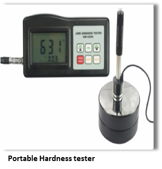
- Portable Hardness Tester.